Data Center, Associate (JNCIA-DC) Questions and Answers
Leaf and spine data centers are used to better accommodate which type of traffic?
Options:
north-east
east-west
north-west
south-east
Answer:
BExplanation:
In modern data centers, the shift toward leaf-spine architectures is driven by the need to handle increased east-west traffic, which is traffic between servers within the same data center. Unlike traditional hierarchical data center designs, where most traffic was "north-south" (between users and servers), modern applications often involve server-to-server communication (east-west) to enable services like distributed databases, microservices, and virtualized workloads.
Leaf-Spine Architecture:
Leaf Layer: This layer consists of switches that connect directly to servers or end-host devices. These switches serve as the access layer.
Spine Layer: The spine layer comprises high-performance switches that provide interconnectivity between leaf switches. Each leaf switch connects to every spine switch, creating a non-blocking fabric that optimizes traffic flow within the data center.
East-West Traffic Accommodation:
In traditional three-tier architectures (core, aggregation, access), traffic had to traverse multiple layers, leading to bottlenecks when servers communicated with each other. Leaf-spine architectures address this by creating multiple equal-cost paths between leaf switches and the spine. Since each leaf switch connects directly to every spine switch, the architecture facilitates quick, low-latency communication between servers, which is essential for east-west traffic flows.
Juniper's Role:Juniper Networks provides a range of solutions that optimize for east-west traffic in a leaf-spine architecture, notably through:
QFX Series Switches: Juniper’s QFX series switches are designed for the leaf and spine architecture, delivering high throughput, low latency, and scalability to accommodate the traffic demands of modern data centers.
EVPN-VXLAN: Juniper uses EVPN-VXLAN to create a scalable Layer 2 and Layer 3 overlay network across the data center. This overlay helps enhance east-west traffic performance by enabling network segmentation and workload mobility across the entire fabric.
Key Features That Support East-West Traffic:
Equal-Cost Multipath (ECMP): ECMP enables the use of multiple paths between leaf and spine switches, balancing the traffic and preventing any one path from becoming a bottleneck. This is crucial in handling the high volume of east-west traffic.
Low Latency: Spine switches are typically high-performance devices that minimize the delay between leaf switches, which improves the efficiency of server-to-server communications.
Scalability: As the demand for east-west traffic grows, adding more leaf and spine switches is straightforward, maintaining consistent performance without redesigning the entire network.
In summary, the leaf-spine architecture is primarily designed to handle the increase ineast-west trafficwithin data centers, and Juniper provides robust solutions to enable this architecture through its switch platforms and software solutions like EVPN-VXLAN.
Exhibit:
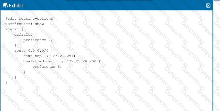
Referring to the exhibit, which next hop will be preferred in the routing table?
Options:
Next hop IP address 172.25.20.254 will be preferred.
Neither next hop will be preferred.
Next hop IP address 172.25.20.200 will be preferred.
Both next hops will be preferred.
Answer:
CExplanation:
In the exhibit, we see a static route configuration with two possible next hops for the default route (0.0.0.0/0):
next-hop 172.25.20.254with the default preference of 7.
qualified-next-hop 172.25.20.200with a preference of 6.
Step-by-Step Breakdown:
Preference Value:In Junos OS, thepreferencevalue is used to determine which route should be preferred in the routing table. The lower the preference value, the higher the priority for the route.
Comparison:In this case:
The next hop172.25.20.254has a preference of7.
Thequalified-next-hop 172.25.20.200has a preference of6.
Preferred Next Hop:Since172.25.20.200has a lower preference (6) compared to172.25.20.254(7), it will be the preferred next hop in the routing table, assuming both next hops are reachable.
Juniper Reference:
Qualified Next Hop: In Junos, static routes with multiple next-hop options are selected based on thepreference value, with the lower value being preferred.
Which three actions are required to implement filter-based forwarding? (Choose three.)
Options:
You must create an instance-type forwarding routing instance.
You must create an instance-type vrf routing instance.
You must create a match filter.
You must create a security policy.
You must create a RIB group.
Answer:
A, C, EExplanation:
Filter-Based Forwarding (FBF) in Junos OS allows traffic to be routed based on specific criteria such as source address, rather than just the destination address. This is useful in scenarios like policy routing or providing multiple paths for different types of traffic.
Step-by-Step Breakdown:
Instance-Type Forwarding:You must create aninstance-type forwardingrouting instance. This routing instance allows for different routing tables based on the incoming packet filter.
Command:
set routing-instances FBF-instance instance-type forwarding
Match Filter:You need to create afilterto match the traffic that will be forwarded according to your custom routing policy. This filter is applied to an interface to determine which traffic will use the custom forwarding instance.
Command Example:
set firewall family inet filter FBF-filter term 1 from source-address
set firewall family inet filter FBF-filter term 1 then routing-instance FBF-instance
RIB Group:ARIB (Routing Information Base) groupis necessary to share routes between the primary routing table and the custom routing instance. This allows FBF traffic to use the routing information from other routing tables.
Command Example:
set routing-options rib-groups FBF-group import-rib inet.0
set routing-instances FBF-instance routing-options rib-group FBF-group
Juniper Reference:
FBF Configuration: Filter-based forwarding requires these specific steps to redirect traffic to a custom routing table based on filter criteria.
A routing policy has been created to advertise OSPF routes in BGP. Which statement is correct in this scenario?
Options:
Apply the policy as an export policy within BGP.
Apply the policy as an export policy within OSPF.
Apply the policy as an import policy within BGP.
Apply the policy as an import policy within OSPF.
Answer:
AExplanation:
When advertisingOSPF routesintoBGP, the appropriaterouting policyshould be applied as anexport policyin BGP.
Step-by-Step Breakdown:
OSPF to BGP Route Advertisement:Routes learned via OSPF (a dynamic IGP) need to be exported into BGP to be advertised to external BGP peers. In Junos OS, this is done usingexport policies.
Export Policies in BGP:An export policy controls which routes are advertised out of a BGP session. In this scenario, the routing policy must be applied toBGP as an export policyto export the OSPF-learned routes to external BGP peers.
Policy Configuration:Example configuration:
set policy-options policy-statement EXPORT_OSPF term 1 from protocol ospf
set policy-options policy-statement EXPORT_OSPF term 1 then accept
set protocols bgp group
This policy ensures that only OSPF routes are exported into BGP.
Juniper Reference:
Routing Policy: Export policies are used in BGP to control route advertisements to peers, including those learned via OSPF.
How does OSPF calculate the best path to a particular prefix?
Options:
It finds the path with the numerically lowest cost.
It finds the path with the shortest autonomous system path.
It finds the path with the least number of hops.
It finds the path with the numerically lowest route preference.
Answer:
AExplanation:
OSPF (Open Shortest Path First)calculates the best path based on thecostof the route, which is derived from the bandwidth of the interfaces along the path.
Step-by-Step Breakdown:
OSPF Path Selection:
OSPF assigns a cost to each link, typically based on the link's bandwidth (higher bandwidth equals lower cost).
The OSPF algorithm computes the shortest path to a destination by adding the costs of all links in the path. The path with thenumerically lowest total costis chosen as the best path.
Cost Calculation:The OSPF cost can be manually adjusted or automatically calculated using the default formula:
Cost=Reference BandwidthLink Bandwidth\text{Cost} = \frac{\text{Reference Bandwidth}}{\text{Link Bandwidth}}Cost=Link BandwidthReference Bandwidth
Juniper Reference:
OSPF Best Path Selection: OSPF selects the path with the lowest cumulative cost, ensuring efficient use of higher-bandwidth links in Junos networks.
What is the definition of a trunk interface on a switch?
Options:
An interface that carries multiple VLANs.
An interface that carries high bandwidth.
An interface that connects directly to powerful servers.
An interface that carries excess traffic.
Answer:
AExplanation:
A trunk interface on a switch is used to carry traffic for multiple VLANs between switches or between a switch and another network device, like a router. Trunk interfaces use 802.1Q tagging to identify which VLAN the traffic belongs to.
Step-by-Step Breakdown:
Trunk Ports:
Trunk ports are typically used for inter-switch links or switch-to-router links where multiple VLANs need to be carried over the same physical connection.
VLAN traffic is tagged with a VLAN ID to ensure that it is properly identified as it crosses the trunk link.
802.1Q VLAN Tagging:
Trunk ports use 802.1Q to tag Ethernet frames with the VLAN ID. This ensures that frames are correctly forwarded to the appropriate VLANs on the other side of the trunk.
Juniper Reference:
Trunk Interface Configuration: In Juniper switches, trunk ports are configured to carry tagged traffic for multiple VLANs, which is essential for interconnecting multiple network segments.
MACsec provides protection against which two types of threats? (Choose two.)
Options:
Data decryption
Playback attacks
Hashing attacks
Man-in-the-middle attack
Answer:
B, DExplanation:
MACsec (Media Access Control Security)provides data confidentiality, integrity, and origin authenticity at Layer 2, protecting against several types of threats.
Step-by-Step Breakdown:
Man-in-the-Middle Attack Protection:MACsec encrypts traffic at Layer 2, preventingman-in-the-middle attackswhere an attacker intercepts and manipulates traffic between two communicating devices. Since the data is encrypted, any intercepted packets are unreadable.
Protection Against Playback Attacks:MACsec also protects againstplayback attacksby using sequence numbers and timestamps to ensure that old, replayed packets are not accepted by the receiver.
Juniper Reference:
MACsec Configuration: Juniper devices support MACsec for securing Layer 2 communications, ensuring protection against replay and man-in-the-middle attacks in sensitive environments.
In the Junos OS, which feature is used to create an alternate next hop with a unique preference for a static route?
Options:
Preference
Resolve
Next-hop
Qualified-next-hop
Answer:
DExplanation:
In Junos OS, thequalified-next-hopfeature is used to specify an alternate next hop for a static route, along with a unique preference value.
Step-by-Step Breakdown:
Qualified-Next-Hop:Aqualified-next-hopallows you to define multiple next hops for a static route, each with its own preference. This provides flexibility by allowing the router to choose the best available next hop based on reachability and preference.
Use Case:If the primary next hop becomes unreachable, the router can automatically switch to the alternate next hop defined by thequalified-next-hopwith a higher preference value.
Command Example:
set routing-options static route 10.10.10.0/24 qualified-next-hop 192.168.1.1 preference 5
set routing-options static route 10.10.10.0/24 qualified-next-hop 192.168.1.2 preference 10
Preference:The next hop with the lowest preference is chosen first. If it becomes unavailable, the router will use the higher preference next hop.
Juniper Reference:
Qualified-Next-Hop: This feature is used to configure backup or alternate next hops for static routes in Juniper devices.
Layer 2 interfaces operate in which two modes? (Choose two.)
Options:
Access
Modular
Trunk
Tagged
Answer:
A, CExplanation:
Comprehensive Detailed Step by Step Explanation with all Juniper Data Center References
Layer 2 interfaces on a switch operate in two key modes:AccessandTrunk.
Step-by-Step Breakdown:
Access Mode:
Access portsare used to connect end devices, like PCs or servers, and they are assigned to a single VLAN. These interfaces handle untagged traffic and do not pass VLAN tags.
Example: A port assigned to VLAN 10 will only handle traffic for that VLAN.
Trunk Mode:
Trunk portsare used to connect switches or other networking devices that need to handle traffic from multiple VLANs. Trunk interfaces carry tagged traffic, allowing multiple VLANs to traverse the same physical link.
Trunk ports typically use802.1QVLAN tagging to differentiate between VLANs.
Juniper Reference:
Access and Trunk Ports: Juniper switches use these modes to manage VLAN traffic at Layer 2, with access ports handling untagged traffic and trunk ports handling tagged traffic from multiple VLANs.
Exhibit:
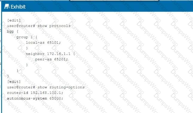
Referring to the exhibit, which statement is correct?
Options:
The configuration will commit successfully and BGP group 1 will operate as IBGP.
The configuration will commit successfully and BGP group 1 will operate as EBGP.
BGP group 1 requires a type external parameter.
BGP group 1 requires a type internal parameter.
Answer:
BExplanation:
In the exhibit, BGP is configured withlocal AS 65101and a neighbor at172.16.1.1inpeer AS 65201. This setup involves two different Autonomous Systems (AS), indicating anExternal BGP (EBGP)configuration.
Step-by-Step Breakdown:
EBGP vs. IBGP:
EBGPis used between routers in different ASes. In this case, the local AS is65101and the peer AS is65201, meaning the BGP session isEBGP.
IBGPis used between routers within the same AS, which is not applicable here as the AS numbers are different.
BGP Group Configuration:
The configuration does not require a type external parameter because Junos OSautomatically recognizes the session asEBGPwhen the local and peer AS numbers are different.
The BGP session will operate as EBGP, and the configuration will commit successfully.
Juniper Reference:
BGP Configuration: In Juniper, EBGP is automatically recognized when the local and peer AS numbers differ, without needing to specify type external.
What are three correct layer names used in legacy hierarchical network design? (Choose three.)
Options:
Access layer
Modular layer
Aggregation layer
Core layer
Function layer
Answer:
A, C, DExplanation:
Inlegacy hierarchical network design, three key layers are used to create a scalable and structured network:
Step-by-Step Breakdown:
Access Layer:
The access layer is where end devices, such as computers and IP phones, connect to the network. It typically involves switches that provide connectivity for devices at the edge of the network.
Aggregation Layer (Distribution Layer):
The aggregation layer (also called the distribution layer) aggregates traffic from multiple access layer devices and applies policies such as filtering and QoS. It also provides redundancy and load balancing.
Core Layer:
The core layer provides high-speed connectivity between aggregation layer devices and facilitates traffic within the data center or between different network segments.
Juniper Reference:
Legacy Hierarchical Design: Juniper networks often follow the traditional three-layer design (Access, Aggregation, and Core) to ensure scalability and high performance.
Which statement is correct about a three-stage IP fabric underlay?
Options:
Every ingress interface into the fabric is only two hops away from the egress interface.
Every spine device can communicate directly with other spine devices.
Every leaf device can communicate directly with other leaf devices.
Every server that connects to a three-stage IP fabric must be multihomed.
Answer:
AExplanation:
In athree-stage IP fabric(also known as a Clos fabric), traffic between any two points (ingress to egress) in the fabric isonly two hops away.
Step-by-Step Breakdown:
Three-Stage IP Fabric:
Leaf Layer: Leaf switches connect directly to servers and edge devices.
Spine Layer: Spine switches provide connectivity between leaf switches but do not connect to each other directly.
Two-Hop Communication:In this architecture, every leaf switch is connected to every spine switch. Therefore, when a packet enters the fabric via an ingress leaf switch, it is forwarded to a spine switch, which then directs the packet to the correct egress leaf switch. This path always involves exactly two hops:
Ingress leaf → Spine → Egress leaf.
Benefits:This consistent two-hop path ensures predictable latency and makes the network highly scalable while maintaining low complexity.
Juniper Reference:
IP Fabric Architecture: This two-hop property of Clos fabrics is a hallmark of spine-leaf designs, as supported by Juniper's QFX and EX switches in data centers.
Exhibit:
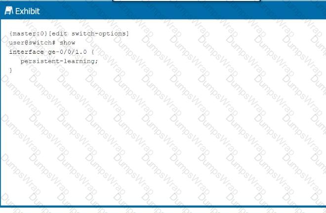
Referring to the exhibit, which behavior does this configuration enable on the ge-0/0/1.0 interface?
Options:
This configuration enables a MAC address learned on the interface to be persistently retained in the Ethernet-switching table, even after a reboot.
This configuration enables the device to place a MAC address that persistently causes network errors into a special protected VLAN.
This configuration enables the device to shut down the interface when a particular MAC address persistently sends broadcast traffic.
This configuration enables the interface to learn and remember MAC addresses, until the device is rebooted.
Answer:
AExplanation:
The configuration in the exhibit shows thepersistent-learningfeature enabled on interfacege-0/0/1.0.
Step-by-Step Breakdown:
Persistent Learning:
Persistent-learningensures that the MAC addresses learned on the interface are retained in theEthernet-switching table, even after a device reboot. This prevents the need to re-learn MAC addresses after the device restarts, improving stability and reducing downtime.
Use Case:
This feature is particularly useful in environments where the re-learning of MAC addresses could cause temporary disruptions or delays in communication, such as in critical Layer 2 network segments.
Command Example:
set switch-options interface ge-0/0/1.0 persistent-learning
Juniper Reference:
Persistent MAC Learning: In Junos, enablingpersistent-learningensures that learned MAC addresses are not lost during reboots, contributing to smoother network operations in environments where stability is crucial.
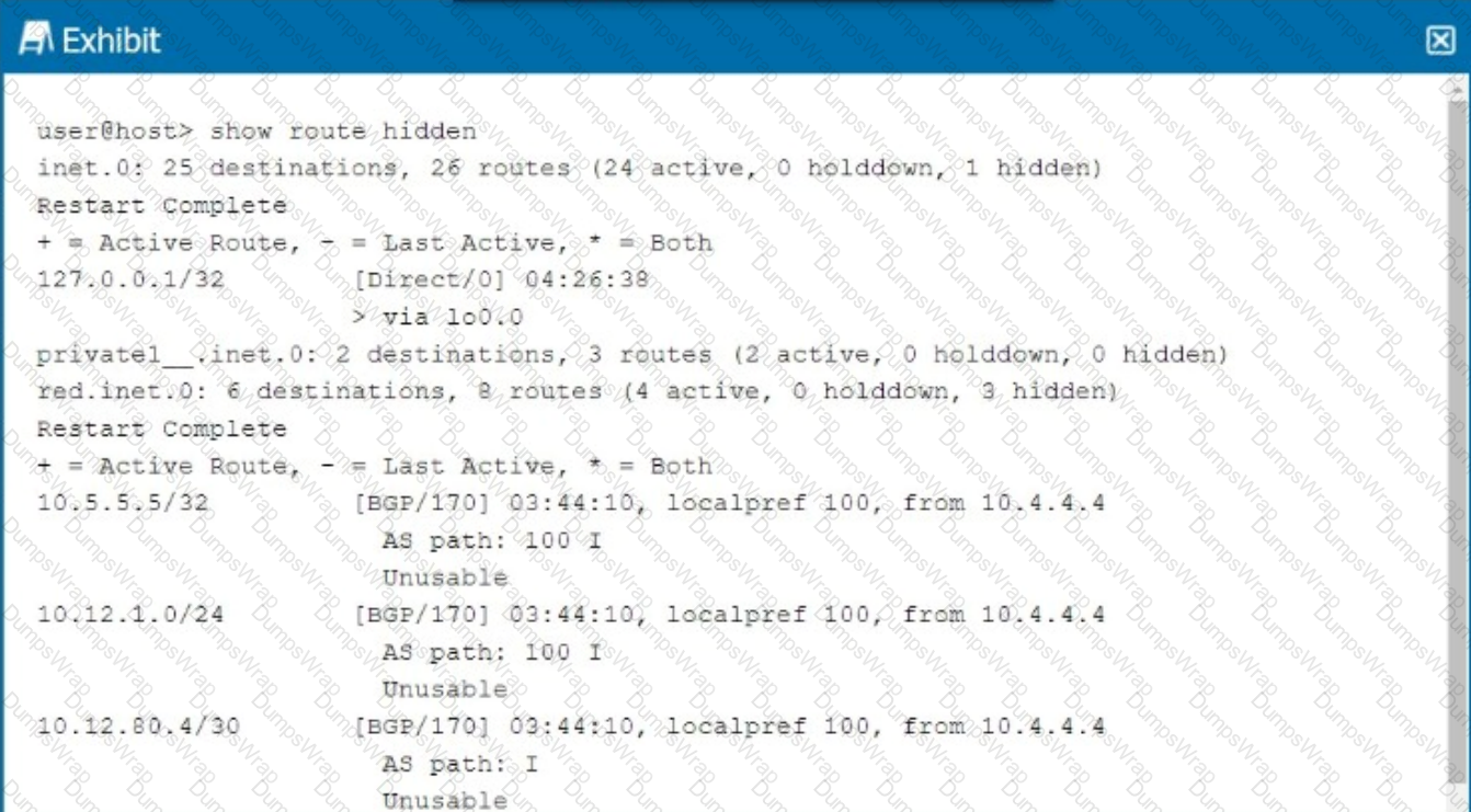
Referring to the exhibit, why are the BGP routes hidden?
Options:
Load balancing is not enabled.
There are too many hops to the destination.
The BGP next hop is unreachable.
Other routes are selected because of better metrics.
Answer:
CExplanation:
In the exhibit, the BGP routes are marked ashidden. This typically happens when the routes are not considered valid for use, but they remain in the routing table for reference. One common reason for BGP routes being hidden is that thenext hopfor these routes is unreachable.
Step-by-Step Breakdown:
BGP Next Hop:In BGP, when a route is received from a neighbor, thenext hopis the IP address that must be reachable for the route to be used. If the next hop is unreachable (i.e., the router cannot find a path to the next-hop IP), the route is marked as hidden.
Analyzing the Exhibit:The exhibit shows that the BGP next hop for all hidden routes is 10.4.4.4. If this IP is unreachable, the BGP routes from that neighbor will not be considered valid, even though they appear in the routing table.
Verification:
Use the command show route 10.4.4.4 to check if the next-hop IP is reachable.
If the next-hop is not reachable, the BGP routes will be hidden. Resolving the next-hop reachability issue (e.g., fixing an IGP route or an interface) will allow the BGP routes to become active.
Juniper Reference:
Junos Command: show route hidden displays routes that are not considered for forwarding.
Troubleshooting: Check the next hop reachability for hidden BGP routes using show route
You want to minimize topology disruptions in your network when the rpd process restarts on a device. Which service would accomplish this task?
Options:
Bidirectional Forwarding Detection (BFD)
link aggregation groups
graceful restart (GR)
Virtual Chassis
Answer:
CExplanation:
Graceful Restart (GR)is a feature that allows a router to maintain forwarding even when the routing process (e.g., the rpd process in Junos) is restarting, minimizing disruption to the network.
Step-by-Step Breakdown:
Graceful Restart Function:During aGR event, the forwarding plane continues to forward packets based on existing routes, while the control plane (rpd process) is restarting. This prevents traffic loss and maintains routing stability.
Minimizing Disruptions:GR is particularly useful in ensuring continuous packet forwarding during software upgrades or routing protocol process restarts.
Juniper Reference:
Graceful Restart in Junos: GR ensures high availability by maintaining forwarding continuity during control plane restarts, enhancing network reliability.
Which statement is correct about areas in OSPF?
Options:
An OSPF area is used to segment Layer 2 broadcast domains.
OSPF areas are used to isolate the effects of a broadcast storm.
OSPF areas are used to reduce the size of the link-state database.
An OSPF area is used to signify the autonomous system to which each device belongs.
Answer:
CExplanation:
InOSPF (Open Shortest Path First), areas are used to segment a network into smaller, more manageable pieces to improve scalability. By dividing a network into areas, OSPF can reduce the size of thelink-state database (LSDB), which helps routers process updates more efficiently.
Step-by-Step Breakdown:
Purpose of OSPF Areas:OSPF areas allow for hierarchical routing within the OSPF domain. Routers in the same area have identical LSDBs, but routers in different areas do not exchange full link-state information. Instead, they exchange summarized routes, which reduces the LSDB size and CPU/memory usage.
Benefits:Reducing the LSDB size improves scalability and ensures faster convergence in larger networks. Area 0 is the backbone area, and all other areas must connect to it, forming a hierarchical structure.
Juniper Reference:
OSPF Configuration: Areas in OSPF are configured to optimize network performance by limiting the scope of link-state advertisements (LSAs) to within an area.
Exhibit:
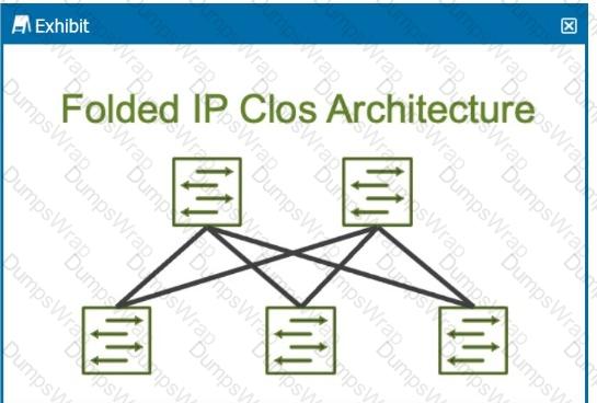
How many stages are shown in the exhibit?
Options:
2
5
6
3
Answer:
DExplanation:
The exhibit shows aFolded IP Clos Architecture, which is also referred to as a3-stage Closnetwork design. This architecture typically consists of two layers of switches:
Spine Layer: The top row of switches.
Leaf Layer: The bottom row of switches.
Step-by-Step Breakdown:
Clos Architecture:A 3-stage Clos network has two types of devices: spine and leaf. In this design, each leaf switch connects to every spine switch, providing a high level of redundancy and load balancing.
Stage Explanation:
Stage 1: The first set of leaf switches.
Stage 2: The spine switches.
Stage 3: The second set of leaf switches.
TheFolded Closarchitecture shown here effectively "folds" the 3-stage design by combining the ingress and egress leaf layers into one, reducing it to two visible layers, but still maintaining the overall3-stage architecture.
Juniper Reference:
IP Clos Architecture: The 3-stage Clos design is commonly used in modern data centers for high availability, redundancy, and scalability.
Which two statements are correct about EVPN-VXLAN overlay networking? (Choose two.)
Options:
It is the only option to provide reachability between servers that reside in the same network segment in a data center.
BGP provides the control plane within the overlay network.
An encapsulation of the original packet is required to transport the packet across the network.
OSPF provides the control plane within the overlay network.
Answer:
B, CExplanation:
EVPN-VXLANis an overlay technology used in data center networks to extend Layer 2 services over a Layer 3 network.
Step-by-Step Breakdown:
BGP Control Plane:BGP (Border Gateway Protocol)is used as the control plane for EVPN-VXLAN. BGP advertises MAC addresses and IP address reachability information across the VXLAN network, enabling efficient multi-tenant Layer 2 connectivity over a Layer 3 infrastructure.
Encapsulation:VXLAN (Virtual Extensible LAN)encapsulates Layer 2 frames into Layer 3 packets. This encapsulation allows Layer 2 traffic to be transported across a Layer 3 network, effectively creating a tunnel for Ethernet frames.
Juniper Reference:
EVPN-VXLAN Configuration: Juniper supports EVPN-VXLAN with BGP as the control plane, allowing scalable Layer 2 connectivity over a routed infrastructure in modern data centers.
What is the main purpose of Bidirectional Forwarding Detection (BFD)?
Options:
to detect network path failures
to determine if the forwarding routes are correct
to detect the forwarding protocol
to determine packet round-trip latency
Answer:
AExplanation:
Bidirectional Forwarding Detection (BFD)is a network protocol used to detect failures in the network path between two devices quickly.
Step-by-Step Breakdown:
Path Failure Detection:BFD provides a low-overhead mechanism for detecting failures in forwarding paths across Layer 3 networks. It is much faster than traditional routing protocol timers and can detect failures within milliseconds.
BFD in Routing:BFD can be integrated with routing protocols like OSPF, BGP, or IS-IS to trigger a faster convergence when a network path goes down.
Juniper Reference:
BFD Configuration: Juniper devices use BFD to monitor network paths and ensure fast failure detection, enhancing network resilience.

