OMG Certified UML Professional 2 (OCUP 2) - Foundation Level Questions and Answers
Choose the correct answer:
Consider the following class diagram:

Which statement is true about the class diagram?
Options:
The preferred age to open a bank account is 18 years old or older
Only customers who are 18 years old or older can open a bank account.
The age condition should only hold when the setAge(Integer) function is called
An object of Customer with age set to 18 or greater will raise an exception.
Answer:
BExplanation:
In UML 2, a class diagram is used to depict the structure of a system by showing the system's classes, their attributes, operations (or methods), and the relationships among the classes. The constraint{age >= 18}in thePersonclass diagram indicates a condition that must hold true for the instances of thePersonclass whenever they are used in the context of aBankAccount. This constraint is an invariant of thePersonclass that specifies the rule for the attributeage.
Now, let's consider the provided options and explain why option B is correct:
A. The preferred age to open a bank account is 18 years old or older – This statement is incorrect because the diagram does not indicate a preference; it indicates a constraint or a rule.
B. Only customers who are 18 years old or older can open a bank account – This is the correct statement. The{age >= 18}constraint next to theageattribute of thePersonclass signifies that any instance ofPersonassociated with aBankAccountmust be at least 18 years old. SincePersonis connected toBankAccountwith the role namecustomer, this implies that only persons who are at least 18 can be customers of a bank account.
C. The age condition should only hold when the setAge(Integer) function is called – This statement is incorrect because the constraint{age >= 18}is not a condition that applies only when thesetAgeoperation is invoked. Instead, it is a class invariant that must always hold true for any instance ofPerson.
D. An object of Customer with age set to 18 or greater will raise an exception – This is incorrect because the UML diagram specifies a constraint, not an exception condition. The constraint ensures validity, not the raising of an exception.
The answer is verified according to the UML 2 Foundation documents, such as the UML 2.5 specification, where class diagrams and constraints are defined. The specification states that constraints are semantic conditions or restrictions expressed in natural language text or in a machine-readable language that must hold true for the system being modeled (UML 2.5 specification, section 7.9).
Choose the correct answer:
Consider the following diagram:
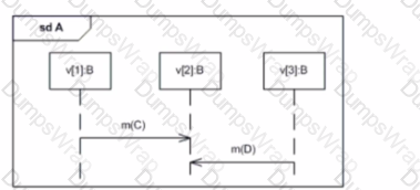
Which statement is always true in the diagram?
Options:
Receiving m{C) must come before sending m(D).
Sending m(D) is the first occurrence of this scenario.
Receiving m{D) is the last occurrence of this scenario.
All occurrences of v[11 will happen before all occurrences of v[3]
Answer:
AExplanation:
The diagram shows a UML Sequence Diagram where two messages are being exchanged between lifelines representing instances of objects:m(C)is being sent fromv1tov2, andm(D)is being sent back fromv2tov1.
In a sequence diagram, the vertical order of message arrows shows the sequence of interactions, with time proceeding down the page. Since the messagem(C)is shown abovem(D), this means thatm(C)occurs beforem(D). The receipt ofm(C)byv2[B]must therefore occur beforev2[B]can sendm(D)back tov1[B].
Therefore, the statement "Receivingm(C)must come before sendingm(D)" is always true in this diagram.
B, C, and D are not necessarily true based on the diagram alone: B) "Sending m(D) is the first occurrence of this scenario" is not depicted. C) "Receiving m(D) is the last occurrence of this scenario" is also not depicted. D) "All occurrences of v[1] will happen before all occurrences of v[3]" is not something we can infer from this diagram since v[3] is not involved in the interactions shown.
Therefore, the correct answer is:
A. Receiving m(C) must come before sending m(D).
Choose the correct answer:
When is a state machine for an object created and ready to accept events?
Options:
by the time the last state ends
immediately after the sequence diagrams start
by the time the object has finished its initialization
when all objects in the system are ready to receive events
Answer:
CExplanation:
In a UML system, the state machine associated with an object becomes active and ready to process events as soon as the object's initialization process is complete. Here's why:
- Object Creation and State Machines: When an object is created, its associated state machine is instantiated along with it. This means the state machine's structural elements (states, transitions, etc.) are established.
- Initialization and the Initial State: During the object's initialization phase, essential attributes and relationships might be set up, and the state machine enters its designated initial state.
- Event Readiness: Once initialization is complete, the object and its state machine are considered "operational" and can respond to events as defined by the state machine's logic.
Why Other Options are Incorrect:
- A. by the time the last state ends: State machines often don't have a designated "last" state. Their execution is based on events and can continue indefinitely. Additionally, a state machine can be ready to handle events long before ending.
- B. immediately after the sequence diagrams start: Sequence diagrams illustrate interactions between objects, but they don't dictate the exact timing of object creation or state machine readiness in the overall system.
- D. when all objects in the system are ready to receive events: While system-wide coordination might be necessary, an individual object's state machine readiness is dependent on its own initialization, not on the state of every other object.
References:
- UML Specification (Superstructure) Version 2.5.1: Specifically, sections covering state machines (https://www.omg.org/spec/UML/2.5.1).
- Practical guides to UML and object-oriented modeling often discuss object creation and state machine lifecycles.
Choose the correct answer:
Consider the following diagram:
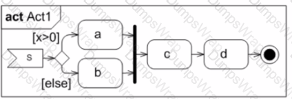
Which statement is true about the execution of Action c?
Options:
After one Signal is received and either a or b is executed, depending on x. it will get executed once
Two or more Signals must be received, depending on x. before c will get executed once.
Action c will get executed twice, since a and b will eventually offer a token.
Nothing can be said The diagram is invalid.
Answer:
AExplanation:
The provided image depicts a block diagram with a signal, decisions, and actions. Here's a breakdown of the elements and why answer choice A is the most accurate:
- Signal: Represented by a vertical arrow labeled "Signal", indicating an external stimulus that triggers the process.
- Decision Diamond labeled "x>0": This diamond represents a decision point based on the condition "x greater than 0". The flow splits into two paths based on whether the condition is True (Yes) or False (No).
- Paths from the Decision:
- Action c: This action is positioned below the decision diamond.
Analysis of Action c's Execution:
- Upon receiving a Signal, the decision point is evaluated.
- Depending on the value of x:
- In either case (True or False), after the corresponding action (a or b) finishes, action "c" is then executed once.
Other Answer Choices Analysis:
- B. Two or more Signals must be received... The diagram suggests execution upon receiving one Signal.
- C. Action c will get executed twice... The diagram indicates c executes only once after either a or b.
- D. Nothing can be said... The diagram conveys a clear sequence of actions based on the signal and the decision.
Choose the correct answer:
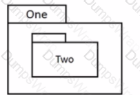
Which diagram is invalid?
A)
B)

C)

D)
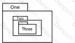
Options:
Option A
Option B
Option C
Option D
Answer:
CExplanation:
Option C shows a UML diagram where a class (One) appears to have an aggregation relationship with itself. In UML, an aggregation is a special type of association that represents a whole-part relationship between the aggregate (whole) and a component part. However, it does not make sense for a class to aggregate itself; such a relationship implies that instances of the same class are parts of each other, which is conceptually invalid.
Let's consider the other options: A) This diagram shows a class contained within another, which is a valid use of nesting classes. B) This diagram shows a composition relationship, which is a form of aggregation with a stronger lifecycle dependency between the whole and the part. This is a valid relationship in UML. D) This diagram shows a class containing two nested classes, one of which contains another nested class. This is also a valid representation of nested classes in UML.
Therefore, the correct answer is:
C. Option C
Choose the correct answer:
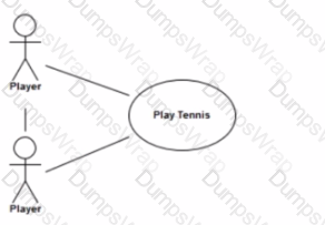
Exactly two Player Instances are involved in the "Play Tennis" Use Case.
Which diagram depicts this scenario correctly?
A)
B)

C)

D)

Options:
Option A
Option B
Option C
Option D
Answer:
CExplanation:
In UML use case diagrams, when specifying the number of actors involved in a use case, a multiplicity marker can be used. The multiplicity marker is a number placed near the actor symbol that denotes how many instances of the actor are involved in the use case.
Option C correctly uses a multiplicity marker of '2' next to the actor 'Player', which indicates that exactly two instances of 'Player' are involved in the "Play Tennis" use case.
Here is a brief explanation of why the other options are incorrect:
A) Option A shows two separate 'Player' actors involved in "Play Tennis" without a multiplicity marker, implying possibly different kinds of players, but does not specify that exactly two instances are required. B) Option B shows two 'Player' actors involved in "Play Tennis" without a multiplicity marker, also not specifying the exact number of instances required. D) Option D uses a multiplicity marker, but it is incorrectly placed near the 'Play Tennis' use case instead of the 'Player' actor, which does not follow UML notation for indicating actor multiplicity.
Therefore, the correct answer is:
C. Option C
Choose the correct answer:
Consider the following class diagram:
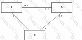
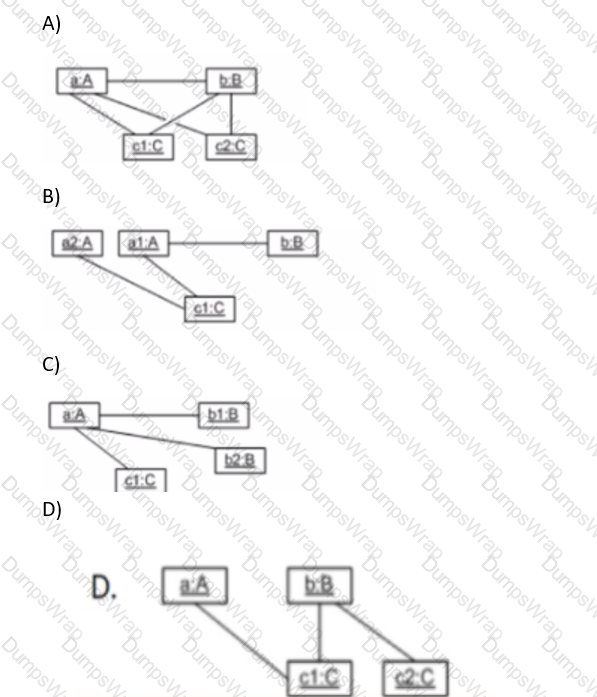
Which object diagram corresponds to it?
A)

B)

C)

D)
Options:
Option A
Option B
Option C
Option D
Answer:
DExplanation:
The question asks to identify which object diagram corresponds to the provided class diagram. In order to verify which object diagram is correct, we must look at the class diagram to understand the relationships and multiplicities between the classes, and then match these with the objects and links in the object diagrams.
The class diagram (not visible in your query but implied to be the reference for the object diagrams provided) must contain three classes, A, B, and C, with specific multiplicity relationships among them. Here’s how we deduce the correct object diagram:
- Multiplicity between A and C is "1..2", which means that for each instance of A there must be one or two links to instances of C.
- Multiplicity between B and C is "0..2", which means that for each instance of B there are zero, one, or two links to instances of C.
- Multiplicity between A and B is "0..1", which indicates that for each instance of A there can be zero or one link to an instance of B.
With these rules, we analyze the object diagrams:
- Option Ahas one instance of A linked to two instances of C, which is correct according to the "1..2" multiplicity. However, there are two instances of B (b1 and b2) each linked to a single instance of C (c1), which violates the "0..2" multiplicity rule because it implies there should be two links from c1 to the B instances (b1 and b2) but instead, there are two separate links to the same instance of C (c1), which is not allowed.
- Option Bhas similar issues where two instances of A (a2 and a1) are linked to a single instance of C, which violates the "1..2" multiplicity rule.
- Option Cshows each instance of A and B linked to their own separate instances of C. This violates the "1..2" multiplicity between A and C since there is only one link from A to C and does not show the possibility of two links which the multiplicity "1..2" would allow.
- Option Dshows a single instance of A linked to two instances of C (c1 and c2), which satisfies the "1..2" multiplicity. Additionally, there is a single instance of B linked to one of the instances of C (c1), satisfying the "0..2" multiplicity. The A instance has no direct link to the B instance, which is allowed because the "0..1" multiplicity permits zero links between instances of A and B.
Based on this analysis, the only object diagram that satisfies all the multiplicity constraints of the class diagram isOption D.
The verification of the answer can be cross-checked with the UML 2 Foundation documentation, specifically in the section dealing with object diagrams and their correlation with class diagrams, which will confirm that object diagrams represent instances of classes and must comply with the multiplicities defined in the class diagram they are derived from. Multiplicity notation and interpretation are fundamental concepts in UML and are well documented in the UML specification by the Object Management Group (OMG).
Choose the correct answer: Which technique does Abstraction incorporate?
Options:
agile modeling
information hiding
complexity coupling
context-driven decision making
Answer:
BExplanation:
Abstraction in UML and software modeling often incorporates the technique of information hiding. Information hiding is a principle that supports abstraction by ensuring that unnecessary details about software components are not exposed to other parts of the system. This encapsulation strengthens modularity and keeps various parts of the program independent of one another, which simplifies complexity in large systems. Abstraction and information hiding are closely related; abstraction focuses on the high-level structure of the system, while information hiding protects the internal states and functionality of components, allowing changes without extensive impact on other system parts.
Choose the correct answer:
Consider the following diagram:
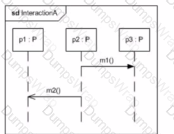
Whichdiagram presents a view of interactionA thatis consistent with the one shown above?
A)
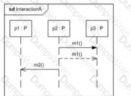
B)
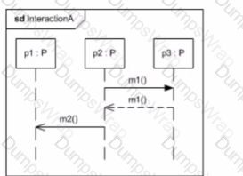
C)
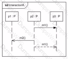
D)
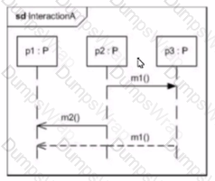
Options:
OptionA
OptionB
OptionC
OptionD
Answer:
DChoose the correct answer:
Consider the following diagram;
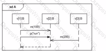
What is the minimum number of occurrences that must happen before the reception of m(200)?
Options:
0
2
4
5
6
Answer:
BExplanation:
The diagram shown is a UML Sequence Diagram, which is used to depict the interaction and order of messages between objects.
In the given diagram, we can see two occurrences of the message 'm' with different parameters (100 and 200), and one occurrence of the message 'p' with the parameter "run".
To determine the minimum number of occurrences that must happen before the reception of 'm(200)', we look at the order of messages:
- The message 'm(100)' must occur.
- The message 'p("run")' must occur after 'm(100)' and before 'm(200)'.
These two occurrences are the minimum necessary before 'm(200)' can be received by the object. The dashed line represents a return message, which does not count as an occurrence for this purpose.
Therefore, the correct answer is:
B. 2
Choose the correct answer:
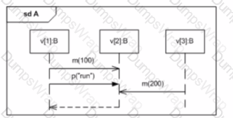
Which element in the following sequence diagram could correspond to a signal?
Options:
v
B
m
p
Answer:
DExplanation:
In UML sequence diagrams, a signal is typically represented as an asynchronous message without a return value. Asynchronous messages are often denoted with an open arrowhead, and they can represent the sending of a signal.
Looking at the diagram provided, 'p' is sent from 'v2[C]' to 'v3[B]' with an open arrowhead, which indicates that it is an asynchronous message. This fits the common representation of a signal, as it does not expect a response.
'A', 'B', and 'C' do not represent signals in the context of a sequence diagram: A) 'v' is not shown in the diagram; it might refer to a lifeline, which is not a signal. B) 'B' refers to a class or object type and not a message or signal. C) 'm' is represented as a synchronous message (as it has a return arrow), which is not typical for signals.
Therefore, the correct answer is:
D. p
Choose the correct answer:

Which elements in the diagram are Features of the Car class?
Options:
drive(), Car
stop(). driver
name. stop()
driveO, stop(). Person
Answer:
DExplanation:
In UML, the features of a class are the combined set of attributes (properties) and operations (methods) that are defined for that class. A feature is a characteristic that classifiers (like classes) can possess. In the context of UML, operations are considered behavioral features, while attributes are considered structural features.
Let's analyze the given options in the context of the Car class:
A. "drive()" is an operation (method) of the Car class, but "Car" itself is the name of the class, not a feature.
B. "stop()" is an operation of the Car class, but "driver" is a role name for an association, not a feature of the Car class.
C. "name" is an attribute of the Person class, not the Car class. "stop()" is indeed an operation of the Car class.
D. "drive()" and "stop()" are operations of the Car class. "Person" is not a feature of the Car class, but no attributes of the Car class are shown in the diagram, and since features include both operations and attributes, the correct answer from the available options isD. It is understood that operations of a class are features, so the answer includes both operations of the Car class: "drive()" and "stop()".
According to the UML 2 Foundation specification, both structural features (attributes) and behavioral features (operations) are considered features of a class, so the correct answer would be the operations "drive()" and "stop()" since those are the only features explicitly represented in the Car class in the diagram.
Choose the correct answer:
Consider the following diagram:
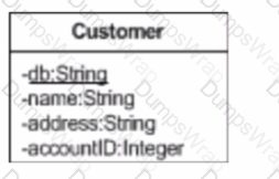
According to the diagram, which statement describes the property db?
Options:
The property db is a primary key
The property db is a static property.
The property db is inherited from a superclass.
The property db is important and is emphasized by the modeler with an underline.
Answer:
BExplanation:
In UML, a static property is one that belongs to the class itself rather than any instance of the class. In UML diagrams, static properties are denoted by underlining the property name.
Now, let's review the options:
A. There is no UML notation in the diagram that specifies whether the property db is a primary key. Primary keys are a database concept and UML does not have a standard way to denote them.
B. The property db is underlined, which indicates that it is a static property. This is the correct UML notation for depicting a class-level attribute.
C. There is no indication in the diagram that db is inherited from a superclass. Inherited properties typically are not underlined (unless they are also static), and there is no superclass shown in the diagram.
D. Underlining in UML does not signify importance or emphasis by the modeler, it indicates that a property is static.
Therefore, the answer isB: The property db is a static property. This is based on standard UML notation as outlined in the UML 2.5 Specification by the Object Management Group (OMG), which dictates that static members (attributes or operations) are underlined in class diagrams.
Choose the correct answer:
Why are abstractions in a model helpful?
Options:
Abstractions add the full detail to the model.
Abstractions can express or suppress detail as needed.
Abstractions can be taken out and the model still makes sense.
Abstractions are not helpful, but rather a distraction in models.
Answer:
BExplanation:
Abstractions in a model are helpful because they can express or suppress detail as needed. This capability is essential in managing complexity in a model by focusing on the high-level, essential aspects of the system while omitting or simplifying the less critical details. This selective detail management aids in understanding and analyzing the system’s core functionality without getting overwhelmed by its intricacies. Abstractions facilitate clearer communication, more focused analysis, and more efficient system design by highlighting the most relevant aspects of the system in various contexts.
Choose the correct answer: Consider the following scenario:
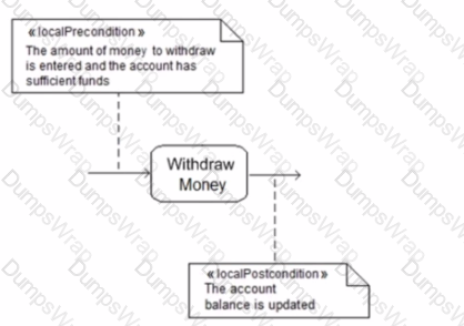
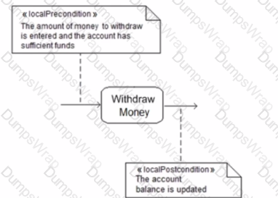
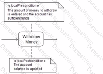
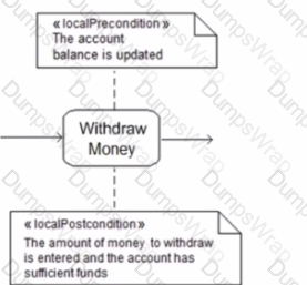
The "Withdraw Money" action can only be executed after the amount to withdraw is entered and the account contains sufficient funds. After the action is executed, the account balance is updated.
Which diagram models this scenario
A)

B)
C)
D)
Options:
Option A
Option B
Option C
Option D
Answer:
CExplanation:
The correct answer is Option C based on the UML 2 Foundation concepts for activities and pre/postconditions.
Analysis of the Diagram in Option C:
- The diagram depicts an activity named "Withdraw Money".
- There are two diamonds preceding the activity, representing preconditions. Preconditions are conditions that must be true before the activity can be executed.
- The text within the first diamond indicates that "the amount of money to withdraw is entered".
- The text within the second diamond indicates that "the account has sufficient funds".
- This aligns with the scenario where the user must enter a withdrawal amount and the account must have enough money to cover the withdrawal before the "Withdraw Money" activity can proceed.
- Following the activity, there's a diamond labeled "postcondition," indicating a condition that becomes true after the activity is completed.
- The text within the postcondition diamond states that "the account balance is updated." This reflects the scenario where the account balance is updated after a successful withdrawal.
Comparison with Other Options:
- Option A, B, and D do not explicitly show preconditions and postconditions using the diamond notation, making them less suited to represent the scenario where certain conditions need to be met before and after the action.
References
- UML 2.5.1 Specification (Superstructure): Sections on Activity Diagrams and Pre/Postconditions https://www.omg.org/spec/UML/2.4/Superstructure/PDF
Choose the correct answer:
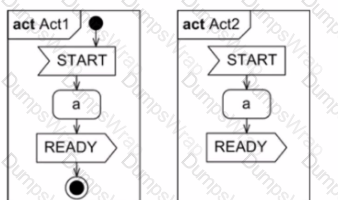
Consider the following two diagrams:
Which description of these diagrams is true?
Options:
In both diagrams, the activity will end after action READY and no further signals will be accepted.
Initial and final nodes are optional. Therefore the execution semantics of both diagrams are equivalent.
In diagram Act1. action a can get executed once. In diagram Act2. action a can get executed many times.
Diagram Act2 is incomplete: It should get completed with exactly one start and at minimum one final node. If this would be done, both diagrams become equivalent.
Answer:
AExplanation:
- Start Node: Represented by a black circle, indicating the starting point of the activity.
- Action a: Represented by a rounded rectangle, signifying an action or step within the activity.
- Action READY: Another rounded rectangle representing an action.
- End Node: A circle with a black dot inside, marking the end point of the activity.
Based on the common elements in both Act1 and Act2:
- The activity starts at the designated start node.
- It proceeds to action "a".
- Then it moves to action "READY".
- Finally, it reaches the end node, signifying completion.
There are no additional branches or loops that would allow for re-starting the activity or re-executing action "a" multiple times.
Analysis of Other Options:
- B. Initial and final nodes are optional... While it's true that initial and final nodes can be implicit in some cases, well-formed activity diagrams typically include them for clarity. Here, both diagrams have them explicitly.
- C. In diagram Act1. action a can get executed once... There's no basis to claim a difference in the number of executions of action "a" between the two diagrams.
- D. Diagram Act2 is incomplete... Both diagrams seem complete as they have proper start and end nodes, and the flow goes from start to finish without any ambiguity.
Therefore, considering the structure and execution flow, both Act1 and Act2 will end after the "READY" action, and no further signals will be accepted, making answer A the most accurate description.
Choose the correct answer:
In your model, you need to represent accounts.
Which statement supports using a Class, rather than a DataType. lor this purpose''
Options:
The account is uniquely identified by its account number.
The account number can change, but it would still be the same account.
The account needs operations to transfer money into it or to withdraw money
The account has attributes typed by Classes like account_holder; Person or bank_in_Charge Company
Answer:
CExplanation:
In UML, a Class is a template that defines the structure and behavior of objects, whereas a DataType is a type of classifier which specifies a domain of values without identity. Operations (such as money transfers and withdrawals) are behaviors that change the state of an object and, therefore, are defined in Classes rather than DataTypes. This suggests that accounts, which require operations to transfer and withdraw money, should be modeled as Classes.
References:
- UML 2.x Superstructure Specification: Provides definitions for Classes and DataTypes, and details the circumstances under which each should be used. It specifically states that Classes can have operations while DataTypes cannot.
- UML 2.x Infrastructure Specification: This foundational document provides an in-depth explanation of UML modeling constructs, supporting the use of Classes when operations are needed to manage an object's state.
Choose the correct answer:
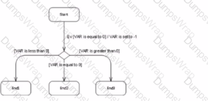
The state machine in the diagram below is in the Start state when an event of type Ev occurs. At that time, the value of local variable VAR is equal to zero.
Which stale will the state machine be in after the run-to-completion step triggered by this event completes?
Options:
End1
End2
End3
Start
Answer:
CExplanation:
UML 2 state machine concepts, here's the analysis of the state machine's behavior after the event and the most likely answer:
State Transition Triggered by Event Ev:
The state machine starts in the "Start" state. When the event "Ev" occurs, there's a transition leaving "Start" with a condition "[VAR is equal to 0]".
Value of Local Variable VAR:
The prompt specifies that the value of local variable VAR is equal to zero at the time of the event.
State Transition Evaluation:
Since the condition "[VAR is equal to 0]" is true (given VAR's value is zero), the transition from "Start" to state "State1" is triggered.
Completion of Run-to-Completion Step:
Upon reaching "State1", there are no further outgoing transitions or events to consider. "State1" itself has no exit actions specified. Therefore, the run-to-completion step reaches its end at "State1".
Most Likely Answer:
Based on the analysis above, the most likely answer is:
C. End3
Explanation for Other Options:
- A. End1: There's no direct path from "Start" to "End1".
- B. End2: Similar to option A, there's no transition leading to "End2" when the event occurs and VAR is zero.
- D. Start: The state machine transitions out of "Start" upon the event "Ev". It won't return to "Start" without another transition.
Possible Ambiguity:
It's important to note that state machines can involve complex logic and actions within states. While "State1" appears to be a terminal state in this case, it's conceivable that there could be hidden actions within "State1" that modify VAR or trigger further transitions. The prompt and the provided image don't provide enough information to definitively rule out such possibilities.
Considering the Absence of Mentioned Ambiguity:
Assuming there are no such hidden actions or unspecified behaviors within "State1", then answer C (End3) is the most reasonable conclusion based on the information available in the prompt and image.
Choose the correct answer:
Which UML term pair captures complementary ways of looking at a relationship?
Options:
include / extend
use / implement
dependency / trace
aggregation / composition
generalization / specialization
Answer:
DExplanation:
The UML term pair that captures complementary ways of looking at a relationship is "aggregation / composition". Both terms describe types of associations between classes but differ in the degree of ownership and lifecycle dependency between the involved objects. Aggregation implies a weaker relationship where the parent class contains or is linked to other classes but does not strictly control their lifecycle (e.g., a university and its students). Composition, on the other hand, implies a stronger relationship where the parent class has full responsibility for the lifecycle of the associated classes (e.g., a house and its rooms). Understanding these relationships helps model systems more accurately in terms of object ownership and lifecycle management.
Choose the correct answer:
Consider the following diagram:
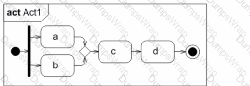
Which statement is true about the execution of Action c?
Options:
It will never get executed, since the parallel flow is not synchronized.
It will get executed one time, since it has one incoming control flow.
It will get executed two times, since two tokens are offered to it
Nothing can be said. The diagram is invalid.
Answer:
CExplanation:
In the provided activity diagram, let’s analyze the execution of Action c:
- Tokens and Control Flow:
- Action c:
- Parallel Flow:
Therefore, the correct statement is that Action c will get executed two times, as indicated by the presence of two tokens offered to it.
For further understanding, you can refer to UML 2 documentation on activity diagrams, which explains the semantics of tokens, control flows, and execution of actions1. Remember that tokens play a crucial role in determining the execution behavior of actions in parallel flows.
Choose the correct answer:
Consider the following diagram:
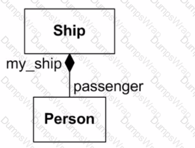
What does the filled diamond mean?
Options:
A Ship-instance is responsible for the existence of the Person-instances linked to it.
Class Person's existence depends on the ship. It will get deleted when the ship gets deleted.
It is a modeling placebo It does not have any influence on the structure of the instances of Ship or Person.
Class Ship owns an attribute passenger of Type Person. The ownership of attribute my_ship is undefined.
Class Person owns an attribute my_ship of Type Ship. The ownership of attribute passenger is undefined.
Answer:
AExplanation:
In UML, a filled diamond represents a composite aggregation, also known as a composition. It indicates a whole-part relationship with strong ownership and coincident lifetime of the parts with the whole. Here's what it means in relation to the options provided:
A. This is partially correct. A filled diamond indeed indicates that the Ship instance is responsible for the existence of the associated Person instances, but it is not complete as it does not explicitly state that the Person instances will be deleted when the Ship instance is deleted.
B. This option is the most accurate. A filled diamond represents a composite aggregation, which means that the existence of the Person instances (parts) isdependent on the Ship instance (whole). When the Ship instance is deleted, so are the Person instances it contains.
C. The filled diamond is not a placebo; it has a well-defined meaning in UML, indicating strong ownership and lifecycle dependency between the whole and the part.
D. While the filled diamond does indicate ownership, it specifies more than just an attribute relationship; it indicates that the Ship class has a composition relationship with the Person class. This means that the Ship object contains Person objects as parts of itself, not just as an attribute reference.
E. The filled diamond is connected to the Ship class, not the Person class, so this statement is incorrect. The composition relationship is from Ship to Person, not the other way around.
Based on the UML specification for composite aggregation, the most accurate statement isB: Class Person's existence depends on the ship. It will get deleted when the ship gets deleted. This aligns with the definition of composite aggregation, where the part's lifecycle is dependent on the whole's lifecycle.
Choose the correct answer:
Suppose you are using a programming language that knows the following basic types: byte, short, and long.
Which diagram defines them:
A)

B)

C)
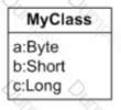
D)

Options:
Option A
Option B
Option C
Option D
Answer:
AExplanation:
In UML, basic types like byte, short, and long are represented as DataType elements. These are typically used to specify the types of attributes, parameters, or return values of operations in a model. Option A shows three separate classes named Byte, Short, and Long, which would represent these as distinct data types within the UML model.
Option B incorrectly uses stereotypes on objects, which is not the correct UML representation for data types. Option C shows a class with attributes of different types, but it does not define these types as basic types. Option D is incorrect because it uses stereotypes on DataType elements, which is not the standard way to represent basic types in UML.
According to the UML 2.5 specification, DataTypes are a kind of classifier that specifies a domain of values without identity (section 10.5.8). DataTypes are not classes; they do not have operations and cannot have instances that maintain an identity.
Choose the correct answer:
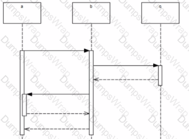
How many execution occurrence specifications are there in total on the diagram below?
Options:
0
1
2
3
4
5
7
Answer:
DExplanation:
An execution occurrence specification in UML sequence diagrams is represented by a thin rectangle on a lifeline. It shows that an instance is performing an action over a period of time.
In the provided sequence diagram, we can see three such thin rectangles on lifeline 'b', which indicates that there are three execution occurrence specifications.
- One for the message that comes from 'a' to 'b'.
- Another one for the message that 'b' sends to 'c'.
- And the last one for the return message from 'c' to 'b'.
There are no execution occurrence specifications on lifelines 'a' and 'c'.
Therefore, the correct answer is:
D. 3
Choose the correct answer:
Consider the following diagram:
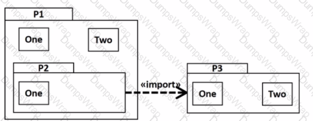
Which element(s) from P3 are visible inside P2 without using a qualified name?
Options:
None
One
TWo
One and Two
Answer:
BExplanation:
In UML, the<<import>>relationship indicates that the namespace of the target element (in this case,P3) is added to the namespace of the source (in this case,P2). However, it's important to distinguish between different types of imports. There are two types of import relationships:
- Public Import: IfP2were to importP3publicly (using<
>), then all public members ofP3would become accessible toP2as if they were part ofP2. - Private Import: IfP2were to importP3privately (using<
>), then the public members ofP3are only accessible withinP2and not to elements that useP2.
Given the diagram, it seems thatP2is importingP3(the nature of the import, public or private, is not explicitly mentioned). Assuming it is a public import and considering thatP2itself is withinP1, which is the higher-level package, thenP1has visibility over its own contents as well as any elements imported intoP2.
ElementOneinP3has the same name asOneinP1, and typically in UML, when an element is imported into a namespace where an element with the same name exists, the imported element is not accessible without a qualified name to avoid ambiguity. However, sinceP2is withinP1, it could be argued thatOneinP3, when imported, would effectively "merge" withOneinP1, thereby makingOnevisible insideP2without a qualified name due to its presence in the higher-level packageP1.
Therefore, the correct answer is:
B. One
Choose the correct answer:
How many class instances can be shown on an Object Diagram?
Options:
0
1
1..*
0..*
Answer:
DExplanation:
In UML, an Object Diagram is a type of static structure diagram that shows a snapshot of the detailed state of a system at a point in time. It focuses on some particular set of objects and attributes, and the links between them. When it comes to the number of instances that can be represented in an Object Diagram, it can range from zero (in cases where the diagram is used to show that no instances of a class exist under certain conditions) to many instances. Therefore, an Object Diagram can show 0 instances, 1 instance, or many instances, which is represented by the multiplicity notation 0..*.
Therefore, the correct answer is:
D. 0..*
Choose the correct answer: Consider the following diagram:

Options:
0
1
2
3
5
Answer:
EExplanation:
The correct answer is E. 5. Based on the image you provided, the diagram depicts the following sequence of steps involved in creating an order:
- Create Order: This signifies the initiation of the order process.
- Fill Order Request: This step likely involves gathering information or processing details about the order.
- Create Invoice: An invoice is typically generated after an order is finalized.
- Notify Customer: The customer is informed about the order, possibly confirmation or receipt.
The key here is that the process starts with creating the order (step 1) and ends with notifying the customer (step 4). Steps 2 and 3 (filling the order request and creating an invoice) can happen concurrently and don't necessarily follow a specific order in relation to each other.
Therefore, following the logic of the sequence, there are five steps (0-based indexing), making E. 5 the most suitable answer.
Choose the correct answer: Consider the following diagram:

Is this diagram valid?
Options:
No, because a DataType cannot have Associations to a Class.
No, because a DataType cannot have Operations.
No, because a DataType cannot have Attributes.
Yes, it is formally correct.
Answer:
AExplanation:
The provided diagram depicts aDataTypenamed Route with operations, attributes, and associations to aClassnamed City. In UML, aDataTypeis a type of classifier that specifiesthe values that do not have identity (i.e., are not distinguishable from other objects).DataTypesmay contain Attributes and Operations, so options B and C are incorrect.
However,DataTypesshould not have associations toClassesbecauseDataTypesare meant to be value types without identity, and associations typically imply a relationship between instances (which have identity). Thus, the presence of associations from Route to City is not consistent with the definition of aDataType.
References:
- UML 2.x Superstructure Specification: Sections on Classifiers and DataTypes provide definitions of what constitutes aDataTypeand what features they can have. They specifically mention thatDataTypesare kinds of classifiers that do not have identity and are often used to type attributes.
- UML 2.x Infrastructure Specification: This foundational document gives additional context on the semantics of different types of classifiers, includingDataTypes, and how they relate to other elements in a UML model.

